Center of Mass Analysis
Given that we are dealing with multiple components, each with its own orientation and position,
defining a global reference scale and maintaining consistency while translating the local COM into the global COM is key.
All components are analyzed with the assumption that the corner of the base begins at the origin.
Robotic Arm Configuration
The robotic arm consists of the following components:
- Base: Fixed to the rover chassis
- Segment 1: Shoulder joint
- Segment 2: Elbow joint
- Segment 3: Wrist joint
- Hand Assembly: End effector for sample collection
Segments 1, 2, and 3 have a cylindrical geometry.
Assumptions
- The arm components are assumed to have uniform density.
- Since the segments have a cylindrical geometry, the COM of individual segments naturally coincides with the geometric center.
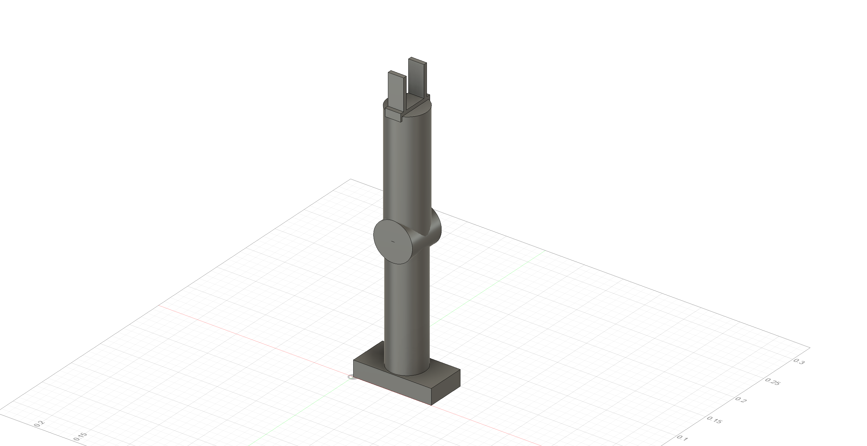
Visual Representation
The robotic arm’s initial configuration is shown below:
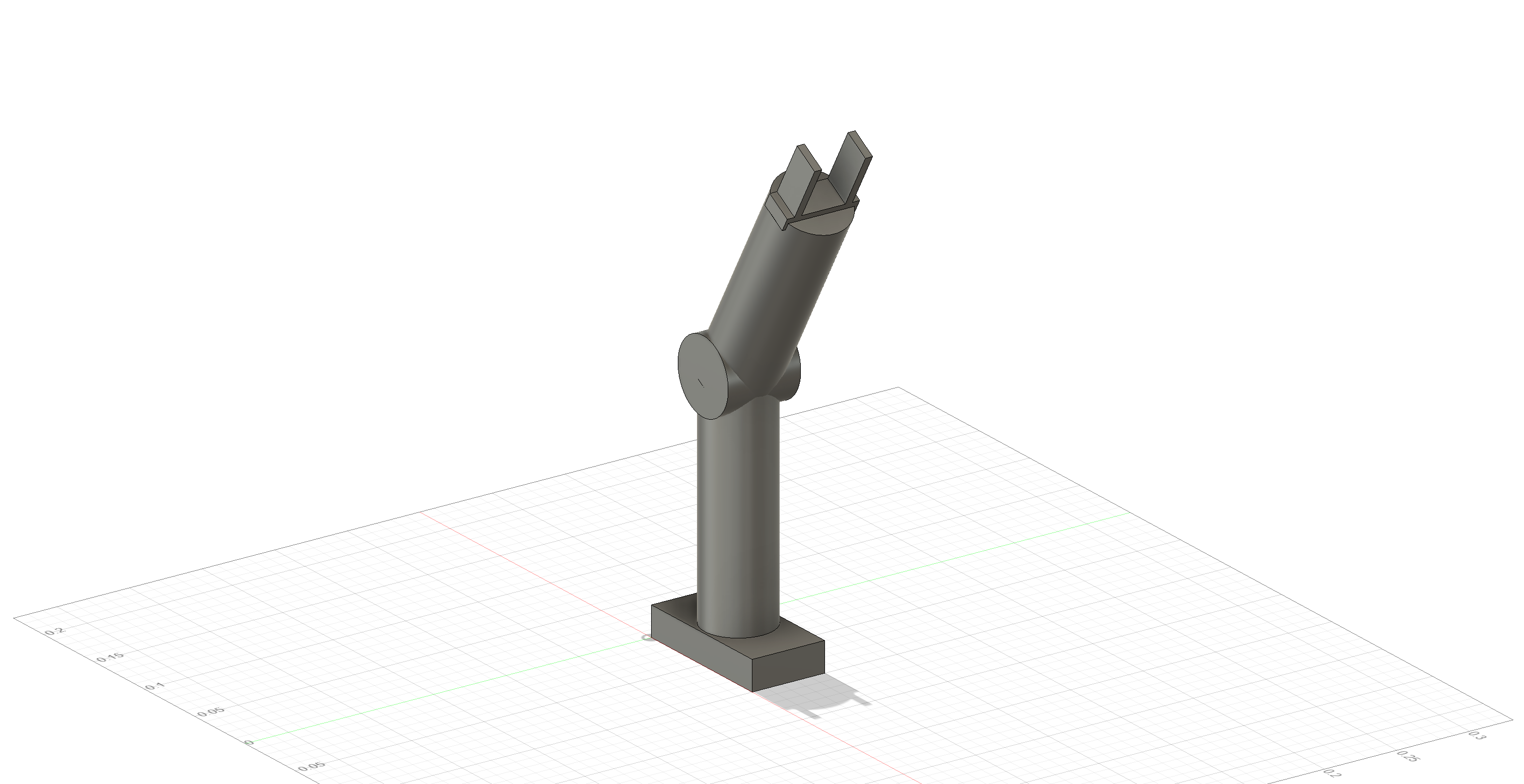
The robotic arm in a different configuration, where the wrist is rotated, is shown below:
Step 1: Defining the Base (Global Origin)
Since the base is a fixed reference point, it serves as the global origin of our coordinate system:
\[(0, 0, 0)\]Step 2: Introducing the Shoulder Joint (Segment 1)
Building from the base, Segment 1 is a cylindrical structure that extends vertically along the Z-axis.
Thus, we align our Z-axis in the direction of Segment 1.
Local Center of Mass (COM) of Segment 1
For a cylinder, the geometric center is at:
\[r_{\text{com, local}} = \left(\frac{l}{2}, \frac{b}{2}, \frac{h}{2} \right)\]However, since Segment 1 is placed directly on top of the base, its X and Y positions align with the origin.
Thus, the Global COM of Segment 1 simplifies to:
Step 3: Introducing the Elbow Joint (Segment 2)
Segment 2 is a cylindrical joint responsible for rotating Segment 3. It is placed on top of Segment 1 and oriented perpendicular to the Z-axis.
Local Center of Mass (COM) of Segment 2
The local COM for Segment 2 is given by:
\[r_{\text{com, local}} = \left(\frac{l}{2}, \frac{b}{2}, \frac{h}{2} \right)\]Global Center of Mass (COM) of Segment 2
To translate the local COM into the global coordinate system, we add the appropriate position offsets.
- Since Segment 2 is placed directly on top of Segment 1, its global X and Y coordinates align with the origin.
- The global Z position is determined by adding the height of Segment 1 to the local Z-component.
Thus, the global COM for Segment 2 is:
\[r_{\text{com, global}} = \left(0, 0, \frac{h}{2} + h_{\text{segment\_one}} \right)\]Step 4: Introducing the Wrist Joint (Segment 3)
Segment 3, referred to as the wrist joint, is placed on top of Segment 2.
Local Center of Mass (COM) of Segment 3
Initially, Segment 3 aligns with the Z-axis of Segment 2, resembling a pole extending from it.
This gives us the local COM before any rotation is applied.
Once Segment 2 rotates, the local COM of Segment 3 will also be rotated accordingly.
The local COM for Segment 3 is:
\[r_{\text{com, local}} = \left(\frac{l}{2}, \frac{b}{2}, \frac{h}{2} \right)\]Global Center of Mass (COM) of Segment 3
To determine the global COM, we add the appropriate position offsets to the local COM.
- The Z offset is the combined height of Segment 1 and Segment 2.
- The X and Y coordinates remain aligned with the origin before rotation.
Thus, the global COM for Segment 3 is:
\[r_{\text{com, global}} = \left(0, 0, \frac{h}{2} + h_{\text{segment\_one}} + h_{\text{segment\_two}} \right)\]Hand Assembly Analysis
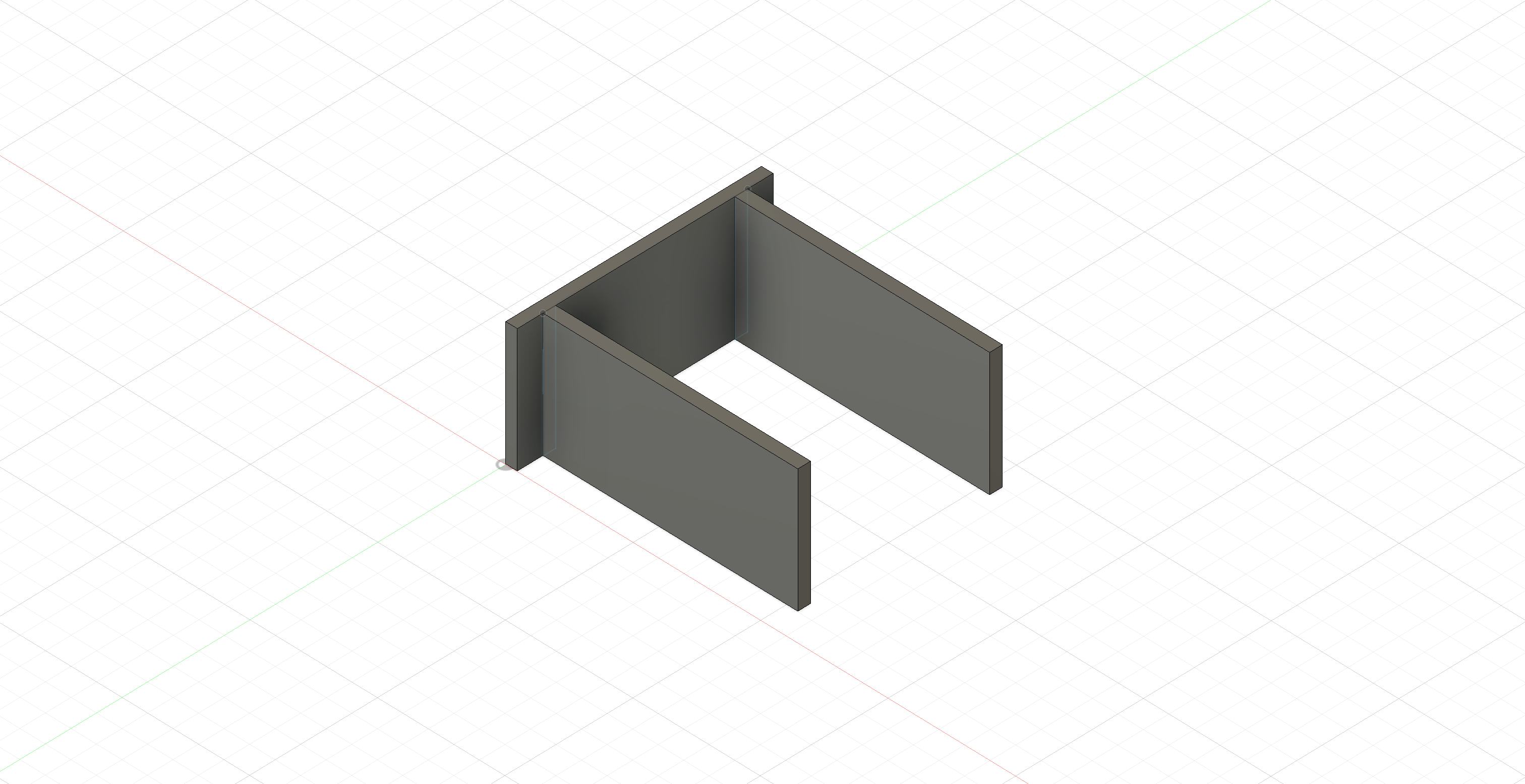
We analyze the center of mass (COM) of the hand assembly in its extended state, translating the individual components as point masses.
Visual Representation
Component Specifications
- Individual masses:
- Base slab: \(m_b\)
- Left slab: \(m_l\)
- Right slab: \(m_r\)
Center of Mass (COM) Analysis for Open Clamp Position
Structural Configuration
-
The base slab starts at the origin:
- Length extends along the x-axis.
- Width extends along the y-axis.
- Height extends along the z-axis.
- Dimensions:
\(l \times b \times h\)
-
The left and right slabs are positioned perpendicular to the base slab along its width (y-axis):
- Length extends along the y-axis.
- Width extends along the x-axis.
- Height extends along the z-axis.
- Dimensions:
\(l \times b \times h\) - The left and right slabs are offset along the y-axis at known distances from the origin.
COM Calculation
Assumptions
- The slabs have a uniform mass distribution.
- The natural COM of each slab is at its geometric center.
For an individual slab, the local COM (before considering positioning) is: \(\left( \frac{l}{2}, \frac{b}{2}, \frac{h}{2} \right)\)
Since the left and right slabs are offset along the y-axis, we must adjust their global COM by incorporating these offsets: \(\left( \frac{b}{2}, \frac{l}{2} + y\_{\text{offset}}, \frac{h}{2} \right)\)
Total Mass
The total mass M is given by: \(M = m_b + m_l + m_r\)
COM Coordinates
The center of mass coordinates are computed as:
-
X-coordinate:
\[x_{\text{com}} = \frac{\sum x_i m_i}{M}\] -
Y-coordinate:
\[y_{\text{com}} = \frac{\sum y_i m_i}{M}\] -
Z-coordinate: \(z_{\text{com}} = \frac{\sum z_i m_i}{M}\)
Thus, the final hand assembly COM is:
\[\text{COM}_{\text{hand assembly}} = (x_{\text{com}}, y_{\text{com}}, z_{\text{com}})\]Sample Calculation for Hand Assembly COM
Translating the Orientation of the Hand Assembly to Align with Design Requirements
Given that the hand assembly is mounted on Segment 3, the following rotations must be applied to align its position with the desired configuration:
Step 1: Rotation About the Z-Axis (90° Counterclockwise)
The first transformation rotates the hand assembly 90° counterclockwise about the Z-axis:
\[\begin{bmatrix} \hat{x}'' \\ \hat{y}'' \\ \hat{z}'' \end{bmatrix} = \begin{bmatrix} \cos\theta & -\sin\theta & 0 \\ \sin\theta & \cos\theta & 0 \\ 0 & 0 & 1 \end{bmatrix} \cdot \begin{bmatrix} \hat{x} \\ \hat{y} \\ \hat{z} \end{bmatrix}\]Step 2: Rotation About the X-Axis (90° Counterclockwise)
Next, the hand assembly is rotated 90° counterclockwise about the X-axis:
\[\begin{bmatrix} \hat{x}'' \\ \hat{y}'' \\ \hat{z}'' \end{bmatrix} = \begin{bmatrix} 1 & 0 & 0 \\ 0 & \cos\theta & -\sin\theta \\ 0 & \sin\theta & \cos\theta \end{bmatrix} \cdot \begin{bmatrix} \hat{x} \\ \hat{y} \\ \hat{z} \end{bmatrix}\]Step 3: Computing the Global Center of Mass
Now that the hand assembly orientation is aligned with the design requirements, we convert its local center of mass (COM) into the global coordinate system.
- Since the hand assembly is mounted on Segment 3, its base sits directly on Segment 3.
- Segment 3 is aligned such that its X and Y coordinates remain at the global origin.
- The height of Segment 3 must be accounted for in the final COM calculation.
Thus, the global COM of the hand assembly is given by:
\[\text{COM}_{\text{hand assembly}} = (0, 0, z_{\text{com}} + h_{\text{segment\_three}})\]*When the wrist is rotated in order to move the hand to perform a task the **COM is rotated about the y-axis hence the global COM rotation is given by.***
\[\begin{bmatrix} \hat{x}'' \\ \hat{y}'' \\ \hat{z}'' \end{bmatrix} = \begin{bmatrix} \cos\theta & 0 & \sin\theta \\ 0 & 1 & 0 \\ -\sin\theta & 0 & \cos\theta \end{bmatrix} \cdot \begin{bmatrix} \hat{x} \\ \hat{y} \\ \hat{z} \end{bmatrix}\]Bringing things together
Now we have a system where each component has its own COM and can be represented as point masses.
Thus the system’s COM can be calculated as:
\[X*{\text{COM, system}} = \frac{1}{M} \sum*{i} m*i \, x*{\text{COM, i}}\] \[Y*{\text{COM, system}} = \frac{1}{M} \sum*{i} m*i \, y*{\text{COM, i}}\] \[Z*{\text{COM, system}} = \frac{1}{M} \sum*{i} m*i \, z*{\text{COM, i}}\]Define the position vector as:
\[\mathbf{r} = x\, \hat{i} + y\, \hat{j} + z\, \hat{k}\]Thus, the system’s center of mass is given by:
\[\mathbf{r}_{\text{COM}} = X_{\text{COM, system}}\, \hat{i} + Y*{\text{COM, system}}\, \hat{j} + Z*{\text{COM, system}}\, \hat{k}\]Alternatively, it can be expressed in the summation form:
\[\mathbf{r}_{\text{COM}} = \frac{1}{M} \sum_{i=0}^{n} m*i\, \mathbf{r}*{\text{COM, i}}\] \[\]