Rotational Dynamics
Topics
-
Spherical cordinate system: Spherical Coordinate System
-
Rigid Body Rotations and Orientation: Rigid Body Rotations and Orientation
Homogeneous Transformation
A matrix that combines rotation and translation into a single 4×4 representation:
\[T = \begin{bmatrix} R & t \\ 0 & 1 \end{bmatrix} = \begin{bmatrix} r_{11} & r_{12} & r_{13} & t_x \\ r_{21} & r_{22} & r_{23} & t_y \\ r_{31} & r_{32} & r_{33} & t_z \\ 0 & 0 & 0 & 1 \end{bmatrix}\]Two-Segment Robotic Arm for Sample Handling
Initial Setup
- The robotic arm starts in its home position, with orientation angles (Yaw, Pitch, Roll) = (0°, 0°, 0°).
- A rock specimen is located uphill and above the rover’s base — simulating a slope or cliff on Mars.
- The arm must reach upward and forward, adjusting its orientation to grasp the rock at the correct angle.
Frame of Reference
We use two conventions to describe the rotation of the arm.
1. Intuitive Frame of Reference (Sequential Rotations)
Using the ZYX Euler angle convention, the arm’s orientation is defined by three rotations:
- Yaw (ψ): Rotation about the Z-axis — base rotation (left/right).
- Pitch (θ): Rotation about the Y-axis — arm raising/lowering.
- Roll (φ): Rotation about the X-axis — wrist twisting.
Rotations are applied intrinsically in the order: Roll → Pitch → Yaw, where each rotation is relative to the current (local) frame.
2. Quaternion Representation
Using the quaternion representation, which is a four-dimensional extension of complex numbers.
Complex numbers are represented as:
\[z = x + iy\]Where:
- \(x\) is the real part.
- \(y\) is the imaginary part.
- \(i\) is the imaginary unit, defined as \(i^2 = -1\).
Complex numbers can be used to rotate 2D vectors (points in the plane) while preserving magnitude by multiplying by:
- \(i\), which rotates the vector counterclockwise by \(\frac{\pi}{2}\) radians, or
- \(e^{i \theta}\), which rotates the vector by an arbitrary angle \(\theta\).
Where:
- \(\theta\) is the angle of rotation.
- \(z\) is the original complex number.
- \(z'\) is the rotated complex number.
Quaternions are represented as:
\[q = w + xi + yj + zk\]Where:
- \(w\) is the real part.
- \(x\), \(y\), and \(z\) are the imaginary parts.
- \(i\), \(j\), and \(k\) are the imaginary units.
- Imaginary units satisfying => \(i^2 = j^2 = k^2 = ijk = -1\) and non-commutative multiplication rules.
Let’s Do the Math
We approach the rotation using sequential intrinsic rotations — each rotation is applied in the rotated (local) coordinate frame.
Step 1: Define the standard rotation matrices
Rotation about the Z-axis (Yaw):
\[R_z(\psi) = \begin{bmatrix} \cos(\psi) & -\sin(\psi) & 0 \\ \sin(\psi) & \cos(\psi) & 0 \\ 0 & 0 & 1 \end{bmatrix}\]Rotation about the Y-axis (Pitch):
\[R_y(\theta) = \begin{bmatrix} \cos(\theta) & 0 & \sin(\theta) \\ 0 & 1 & 0 \\ -\sin(\theta) & 0 & \cos(\theta) \end{bmatrix}\]Rotation about the X-axis (Roll):
\[R_x(\phi) = \begin{bmatrix} 1 & 0 & 0 \\ 0 & \cos(\phi) & -\sin(\phi) \\ 0 & \sin(\phi) & \cos(\phi) \end{bmatrix}\]Applying the Rotations
Given that the arm must pitch upward to reach the rock, we apply a pitch of 90°, i.e., \(\theta = \frac{\pi}{2}\):
\[R_y\left(\frac{\pi}{2}\right) = \begin{bmatrix} 0 & 0 & 1 \\ 0 & 1 & 0 \\ -1 & 0 & 0 \end{bmatrix}\]Now the full orientation of the segment becomes:
\[R = R_z(\psi) \cdot R_y\left(\frac{\pi}{2}\right) \cdot R_x(\phi)\]Matrix Result
After symbolic multiplication:
\[R = \begin{bmatrix} 0 & -\sin(\psi)\cos(\phi) + \cos(\psi)\sin(\phi) & \sin(\psi)\sin(\phi) + \cos(\psi)\cos(\phi) \\ 0 & \cos(\psi)\cos(\phi) + \sin(\psi)\sin(\phi) & -\cos(\psi)\sin(\phi) + \sin(\psi)\cos(\phi) \\ -1 & 0 & 0 \end{bmatrix}\]Using trigonometric identities:
\(\sin(\psi)\cos(\phi) + \cos(\psi)\sin(\phi) = \sin(\psi + \phi)\) \(\cos(\psi)\cos(\phi) - \sin(\psi)\sin(\phi) = \cos(\psi + \phi)\)
We simplify the matrix to:
\[R = \begin{bmatrix} 0 & \sin(\psi + \phi) & \cos(\psi + \phi) \\ 0 & \cos(\psi + \phi) & -\sin(\psi + \phi) \\ -1 & 0 & 0 \end{bmatrix}\]Orientation Check
Looking at the first column of the rotation matrix:
\[\mathbf{R}_{\text{x-axis}}^\top = \begin{bmatrix} 0 & 0 & -1 \end{bmatrix}\]This tells us that the local X-axis is now aligned with the negative global Z-axis.
Let’s explore what happens if we try to apply a further rotation. We’ll consider two cases: one where we yaw before the pitch, and one where we roll after the pitch.
Case 1: Rotate about the local X-axis (i.e., more roll)
This means increasing the roll angle from \(\phi\) to \(\phi + \alpha\):
Using identity:
\[R_x(\phi + \alpha) = R_x(\phi) \cdot R_x(\alpha)\]So, new orientation:
\[M_x = R_z(\psi) \cdot R_y\left(\frac{\pi}{2}\right) \cdot R_x(\phi) \cdot R_x(\alpha)\]Case 2: Rotate about the global Z-axis (i.e., more yaw)
This means increasing yaw from \(\psi\) to \(\psi + \alpha\):
Using identity:
\[R_z(\psi + \alpha) = R_z(\psi) \cdot R_z(\alpha)\]So, new orientation:
\[M_z = R_z(\psi) \cdot R_z(\alpha) \cdot R_y\left(\frac{\pi}{2}\right) \cdot R_x(\phi)\]Comparing the Two
Now we compare:
-
Additional local X-axis rotation:
\[M_x = R_z(\psi) \cdot R_y\left(\frac{\pi}{2}\right) \cdot R_x(\phi) \cdot R_x(\alpha)\] -
Additional global Z-axis rotation:
\[M_z = R_z(\psi) \cdot R_z(\alpha) \cdot R_y\left(\frac{\pi}{2}\right) \cdot R_x(\phi)\]
Because of the special configuration of \(R_y\left(\frac{\pi}{2}\right)\), the effect of applying \(R_x(\alpha)\) after pitch is equivalent to applying \(R_z(\alpha)\) before pitch.
That is:
\[R_y\left(\frac{\pi}{2}\right) \cdot R_x(\alpha) \approx R_z(\alpha) \cdot R_y\left(\frac{\pi}{2}\right)\] \[M_x \approx M_z\]We have lost one degree of freedom— the system can no longer distinguish between the two.
Approaching the problem using quaternions avoids this issue. Quaternions are not subject to gimbal lock and can represent any rotation in 3D space.
Step 1: Represent the 3D vector as a pure quaternion
Vector in 3D space:
\[\vec{v} = (x, y, z)\]It is represented as a pure quaternion:
\[\mathbf{v} = 0 + x\mathbf{i} + y\mathbf{j} + z\mathbf{k}\]or
\[\mathbf{v} = (0, x, y, z)\]Step 2: Define the rotation quaternion
To rotate the vector around an arbitrary axis \(\vec{u}\), by an angle \(\theta\):
We identify the rotation axis vector:
\[\vec{u} = (u_x, u_y, u_z)\]This must be a unit vector.
Define the quaternion components for the rotation:
\[\mathbf{q} = \cos\left(\frac{\theta}{2}\right) + \sin\left(\frac{\theta}{2}\right)(u_x\mathbf{i} + u_y\mathbf{j} + u_z\mathbf{k})\]or in component form:
\[\mathbf{q} = \left(\cos\left(\frac{\theta}{2}\right),\ \sin\left(\frac{\theta}{2}\right)u_x,\ \sin\left(\frac{\theta}{2}\right)u_y,\ \sin\left(\frac{\theta}{2}\right)u_z\right)\]Visual Representation
2D:
3D:
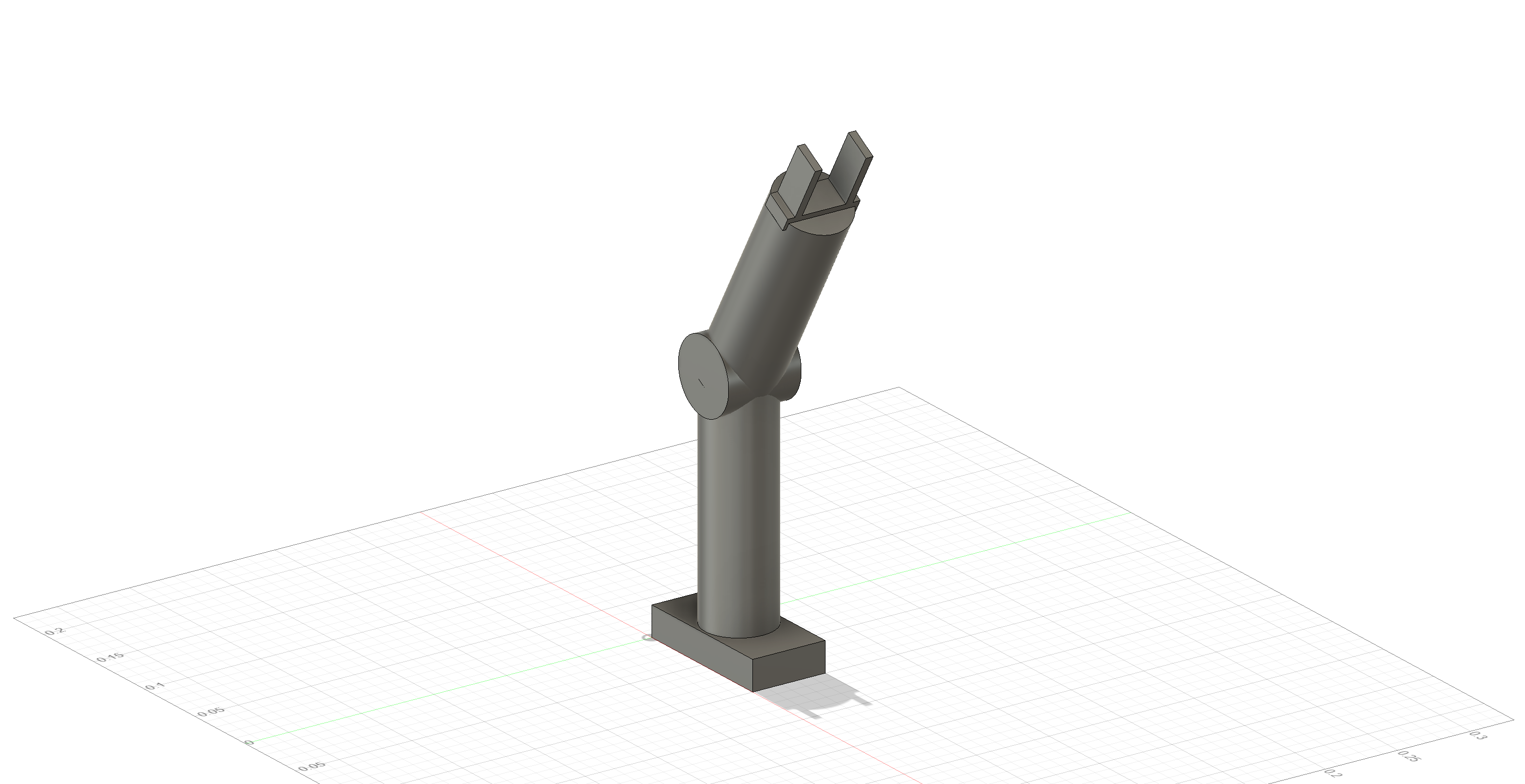
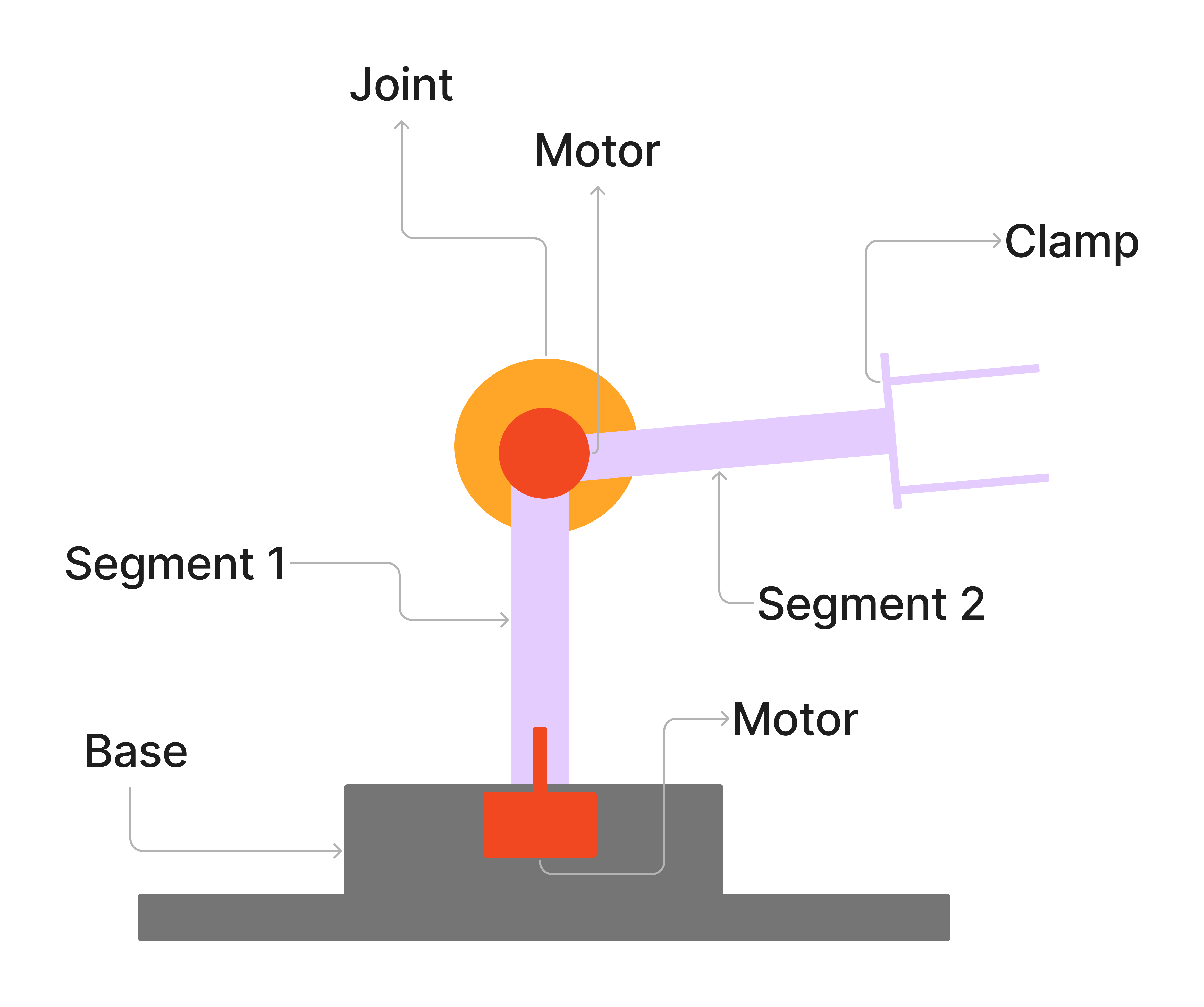
Arm Components
- Base: Fixed to rover chassis
- Segment 1: Shoulder joint
- Segment 2: Elbow joint
- Segment 3: Wrist joint
- Hand Assembly: End effector for sample collection
Physical gemotry of the robotic arm system:
- Segment 1: Cylindrical geometry
- Segment 2: Cylindrical geometry
- Segment 3: Cylindrical geometry
- Hand Assembly: 3 rectangular slabs
- The base slab is fixed to the wrist joint
- The holder slabs are fixed to the base slab and can slide along its length
1. Dynamics Analysis
- Calculate moment of inertia for:
- Both arm segments and the joint
- Hand assembly
- Payload contribution
- Apply Parallel Axis Theorem for offset payloads
-
Determine required torques at both joints
- Rotational Kinematics